Part 1: The Bit
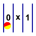
The position of the ball determines its value. The left column is zero, the right is one, and the middle is indeterminate. Balls pass through the middle column only when they are changing state.

We can get a ball to change its state by removing walls and adding ramps. This animation shows a bit being reset to zero.
 Part 2: The Not Gate
The NOT gate is an inverter; it outputs the opposite of the input. To do this with balls, we need two ramps. The ball's velocity allows it to make the jump over the middle.
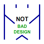
We need to design this carefully because balls enter at a variety of speeds and angles. Having small openings enforces a certain trajectory. Otherwise a ball could bounce to the wrong side, causing an error.
 Part 3: The AND Gate
Now things start to get tricky. A normal AND gate has two inputs, and a single output that is active only when both inputs are active. Since we are using balls, we need to have the same number of inputs as outputs: if two balls go in, two balls better come out.
The simplest solution we thought of is to have a switch where one ball sets the path of the other ball. We call this a 'stated' AND gate, since the switch can flip between its two different states.
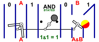
The animation above shows the gate in action. It has two inputs (A,B) and two outputs (A, A&B). The A ball must goes first, flipping the switch, which affects the 1's path for B. That way the B ball becomes A&B, while the A ball remains A.
 Part 4: The XOR Gate:
An XOR gate is active when either of its inputs are active, but not both. It can be thought of as a NOT gate which turns on if the A input is on.
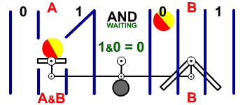
 Part 5: The Waiting AND Gate:
If we did everything with state gates, we would need extra balls to create copies of values. To avoid extra complication, we use a different type switch. This forces the A ball to wait until the B ball arrives.
The animation below is the 'waiting' AND gate. The one's path of the A ball is blocked by a counter-balanced switch. If the A ball is a 1, it has to wait until the B ball drops before becoming A&B. The B ball keeps its value.
The waiting AND introduces a new problem. If the gate is designed poorly, the ball can get stuck. This is known as a crash, and the system will not be able to recover.